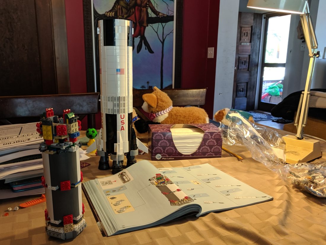
We finished our Lego Saturn V! Just in time to celebrate the 50th anniversary of the moon landing.
I like to pick projects to do with my kids. Sometimes it’s just a puzzle, and other times it has been Lego. This was one of those projects.
You can find a ton of reviews for this set online, and it seems like I am the last person to complete the set. The reviews are true – it’s a great set, well thought out, and very large. You can even add some lights and sound if you want.
Motivating your family
I have found my kids don’t necessarily want to do something if I ask them. Instead, I have had a lot of luck just starting a project in a common room, and they kind of gather on their own. For instance, I’ll start a puzzle and pretty soon someone shows up. They usually start by asking me what I’m doing. They might make fun of it. Soon they start watching. Then they start helping me. Coincidentally, this also works on my significant other 🙂
How to find one
These sets used to be hard to find, but that doesn’t seem to be the case anymore. If you are having a hard time find this set or another set like it, there are some websites that will alert you when a set is back in stock. In hindsight, I probably could have waited longer for a used set to show up online.
If you are looking to save a little money, you might do well to find a used set. For me, I was only interested in the rocket – I did not care too much about the lunar lander and stand. If I would have waited an extra year I could have saved a lot of money. You might do well to find a set that is missing some of these accessories. At least for me, tracking down missing parts can be part of the fun of constructing a set.
Here are some other Lego projects I have worked on:
How I programmed an Arduino to accept a button press and then ignore subsequent button presses
I am working on an art project that involves a button. The button will start the device, but ignore any extra button presses for a set amount of time. This post focuses on my small journey, and a few things I learned along the way.
My Background
I have a very basic knowledge of electronics. I have an Arduino starter kit, and I played around with the tutorials until I understood the basics. After that I moved on. I figured I could always pick it back up again if needed.
The Requirements
Start a garage door opener (I’ll refer to it as the “opener” from now on)
Use the opener’s wired-button terminals/leads/pins to control it. These are the same leads that you would use hook up to a button on the wall in your house to use your garage door opener.
The opener has 2 terminals/leads – if they touch together, the opener will start
Use a button to communicate with the Arduino. It will decide if it should (or should not) use those terminals to start the opener
Hardware
I need 2 buttons: One to communicate with the Arduino, and the other one controlled by the Arduino. To do this I need something called a Relay.
What’s a Relay
A Relay is a fancy switch that is controlled by electricity. It does this with an electromagnet. Imagine a light switch – you add some parts so that if you hold a magnet to one side, the switch will flip. Take the magnet away and the switch flips back off. Wrap that into a box and you have a relay.
If no electricity is running to the Relay, then there is no magnet. The switch is off
If electricity is running to the Relay, then the electromagnet is on. The magnet attracts the switch to the other side and turns the switch on
You can hear a Relay when it switches. It makes a distinct “click” noise. You find them in a lot of everyday things, like your windshield wipers.
That’s the basics. Yet there are a few more features:
The Relay can do the exact opposite. It can be ON when no electricity is running, and turn OFF when the electricity is on
Relays are used to operate high voltage electronics, while protecting sensitive equipment. The Arduino can only handle about 5 volts. It could never power a household light bulb. To do this you wire the light bulb with the full power, and use a relay to control that power. The Arduino is safely behind the Relay, protected from the high voltage.
A relay typically has 5 pins:
Input 1: the positive (+)
Input 2: the negative (-)
a common (or COM): this is one half of the thing you are switching
Normally Closed (or N/C): when power is on, the switch is on
Normally Open (or N/O): when power is off, the switch is on
My Relay had no labels and looked different from most of the tutorials. I figured it out by connecting a couple alligator clips to a 9v battery. After connecting them to the pins on the relay, I listened for the click of the magnetic switch. After that I used my volt meter to determine which pins were Normally-Closed and Normally-Open.
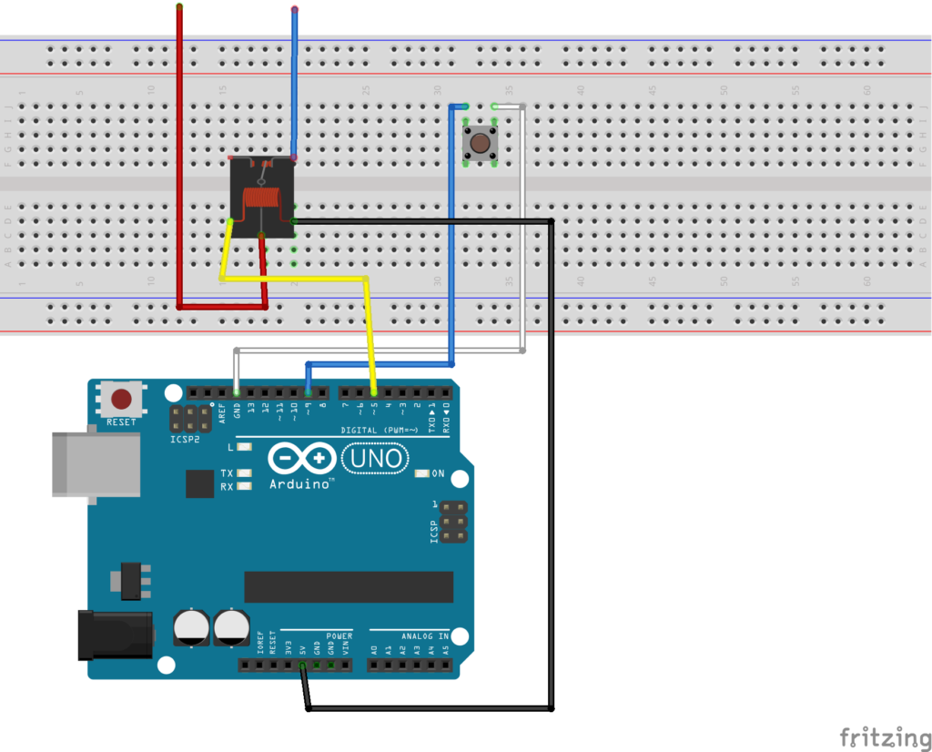
The hardware layout
Relay Setup:
I connected my ~5 on the Arduino to one pin on the relay, and 5v on the Arduino to the other pin
The Common (middle) lead connects to one terminal on the garage door opener
The N/C (Normally Closed) pin connects to the other terminal on the garage door opener
Button Setup:
The button setup is like all the other button tutorials
I connected ground (GRD) on the Arduino to one end of the button
I connected ~9 on the Arduino to the other end of the button
My first time drawing a diagram in fritzing!
The Code
Intended behavior:
When the button is pressed (or LOW) on ~5, I trigger a “button press” using the relay for the garage door opener (it starts)
I then run a delay for a set amount of time
the delay allows my code to ignore everything until after the delay has finished
Quick notes:
I use the built-in LED on the Arduino to show when it is ignoring button presses (LED_BUILTIN)
I write debug messages to the serial. Not a big deal but it makes the code a little more busy looking
/**
 * Ignore button presses after accepting the first, for a set amount of time
 * Jason Jerome
 */

int gDoorPin = 5;
int buttonPin = 9;

String msg = "seconds to wait: ";
int secondsToWait = 20;

void setup()
{
  Serial.begin(9600);
  pinMode(LED_BUILTIN, OUTPUT);
  pinMode(gDoorPin, OUTPUT);
  pinMode(buttonPin, INPUT_PULLUP);

  digitalWrite(gDoorPin, HIGH);
  Serial.println("Hi - ready");
}

void loop()
{
  if (digitalRead(buttonPin) == LOW)
  {
    Serial.println("button pressed");
    digitalWrite(LED_BUILTIN, HIGH);

    startOpener();

    Serial.println(msg + secondsToWait);
    delay(secondsToWait * 1000);

    Serial.println("done - ready for more");
    digitalWrite(LED_BUILTIN, LOW);
  }
}

void startOpener() {
  Serial.println("gDoor - activating");
  digitalWrite(gDoorPin, LOW);
  delay(500);
  digitalWrite(gDoorPin, HIGH);
}
Here’s a video of it in action:
This has been a fun project so far. I’m very happy to have most of the electronics figured out so early in the process. I can now move on to designing and building the other parts!
I built some temporary walls to create an office in my basement.
The Back story
I was renting a small office for contract work, and decided to move home to save some money. The only available space was our unfinished basement. It was too large to keep warm in the winter, so I came up with an idea of creating cheap walls to make a room.
A small office in the basement also had the advantage of creating 2 layers of separation with the house. It’s too easy for someone to accidentally open a door during an important meeting. It’s much harder to open the door to the basement, walk down the stairs, wander over to the corner office, and peak inside.
The wall material is a cheap lightweight sound proofing material called Homasote. It’s a very lightweight highly-compressed paper-mache material. I found a bunch at my local used building materials store.
Step 2: measure your height
I measured the height of the basement ceiling and made each wall an inch shorter. I also made sure I could move them in, out, and around the basement without too much trouble.
Step 3: the frame
I built the frames using 2×2 wood boards. I constructed a simple frame around the edges and then screwed the Homasote sheet to the frame.
Putting it all together
I struggled for a while with how to hold the walls in place. I didn’t want them to fall over. In the article they used furniture levelers, but I found them a little pricey.
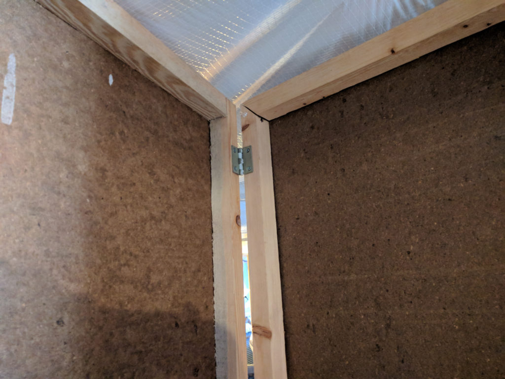
My solution was to build a couple walls at right angles. I then made sure any straight wall was attached to a right-angled wall. In places where a wall was a little wobbly, I wedged a piece of wood perpendicular between the ceiling and wall.
A right-angled wall. For this one I used hinges.
What about a door?
There was no way to create a proper door, but I came up with a good solution. I left a door-sized gap that would serve as the entrance, and hung 2 wool blankets on either side of the doorway. This made for a rather heavy blanket door that did not let in any drafts.
Heat
The basement wasn’t heated, so I used a strategy involving 2 electric heaters to keep warm:
A radiator-style electric heater provided most of the base heat. I had it hooked up to an industrial timer that would turn on the heat a half hour before I started work.
An electric fireplace heater that had a temperature control and remote. I used it to dial in the heat a little better, and as a bonus I had some fake flames to look at for some ambiance.
The office worked very well over the years. I even incorporated a portable air conditioner. Often times I would come up to grab a snack and my wife would remark that she didn’t even know I was home.
If you are looking for a cheap way to create some separation in a room, this could be a good solution for you.